 |
Fuel Cells for Power |
|
|
Fuel Cells for Power |
|
|
Wire Sizing Charts and Wire Gauge Selection Working on a custom electrical installation can be a challenge from the design perspective. Obviously if you’re building a custom wiring harness, you want to be certain to observe the appropriate electrical specifications on wire sizing in order to avoid any future electrical problems in the completed system. Conventional wisdom would dictate that for a given electrical load, operating at a known voltage, over a specific length of wire, that a wire sizing table or wire gauge selection chart would exist, allowing the user to easily select the appropriate gauge wire from this mystery chart. It’s been my experience that this is not exactly the case. Sure, there are several charts and tables out there on the world wide web, but they all seem to contradict each other. Many are very open ended, requiring the user to guess at certain variables. If you happen to select the wrong chart, knowing that current carrying capacity differs greatly when using 120VAC and 12VDC systems so how can you ensure that you’re working with good data when you design your project? |
|
||
|
|
||||
|
|
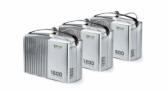 EFOY 600, 1200, and 1600 Fuel Cells 44cm x 20cm x 28cm 7.5 kg |
Well, based on everything I've been able to dig up, incorporating my own common
sense filter, I’ve settled on two approaches that I feel will work best
for my particular applications. They are included here as a reference
for me and me alone. This page should not be considered an authoritative
source on the selection of appropriate wire gauge for any particular
application. I would suggest consulting other sources such as wiring
codes and manufacturers recommendations on the piece of equipment you
are installing for more details and I am in no way recommending what
wire size one might use for a specific application. The information
contained on this page is provided as-is and without any guarantee as to
it's accuracy or completeness. Any issues caused by the use of this
information are not my fault. Use this information at your own risk. |
||||
|
Wire Sizing Approach: Voltage Drop Index I’ve seen this one is a couple places on the internet. It uses a chart based on Voltage Drop Index to determine copper wire size. STEP 1: Calculate the Voltage Drop Index of the application. AMPS x FEET = Voltage Drop % VOLT DROP x VOLTAGE Index (VDI) VDI – Voltage Drop Index (a reference number based on resistance of wire) FEET – One-way wiring distance % voltage drop – 3% is typical, therefore 3 is used STEP 2: Determine Appropriate Wire Size from Chart. Compare the calculated VDI with the VDI listed in the chart to determine the closest wire size. Starting at the VDI column, run down the list of numbers arriving at the value which is greater than the calculated VDI. Move left to the Ampacity column to verify that the total current of the circuit does not exceed the maximum allowable amperage of the wire size for that row. If it does, move down until the wire ampacity exceeds the circuit amperage. Finally move left to the Wire AWG column to select the wire size.  |
Wire Sizing Approach: Blue Sea Systems I found this one from Blue Sea Systems, a leader in marine electrical products. For this approach, I utilize the chart below in conjunction with some simple calculations to determine the appropriate copper wire size. I’m sure to make the necessary adjustments to the procedure, which is intended for marine use, to suit my own application. STEP 1: Calculate the maximum sustained amperage of the circuit and measure the length of the circuit from the power source to the load and back. STEP 2: Decide whether the circuit runs in an engine space or non engine space. Engine spaces are assumed to be at 50 degrees C, non engine spaces are assumed to be at 30 degrees C. STEP 3: Multiply the maximum current times the length of the circuit to calculate Famps (feet x amps). STEP 4: Using a 3% voltage drop, start at the column which has the right voltage and run down the list of numbers arriving at the value which is greater than the calculated Famps. Move left to the appropriate Ampacity column to verify that the total current of the circuit does not exceed the maximum allowable amperage of the wire size for that row. If it does, move down until the wire ampacity exceeds the circuit amperage. Finally move left to the Wire Size column to select the wire size.  |
||||
|
Examples: 1. A 12-volt system with a 15 amp load, 15’ away. (15A x 15ft) / (3 x 12vdc) = 6.25 A wire size of 8AWG is recommended by the chart. 2. A 24-volt system with a 10 amp load x 12’ away (10A x 12ft) / (3 x 24vdc) = 1.67 . A wire size of 14AWG is recommended by the chart. |
Examples: 1. A 12-volt system with a 15 amp load x 30’ length = 450Famps. A wire size of 8AWG is recommended by the chart. 2. A 24-volt system with a 10 amp load x 24’ length = 240Famps. A wire size 14 is recommended by the chart. |
||||
|
A Production of Madness
Unwatched LLC |